
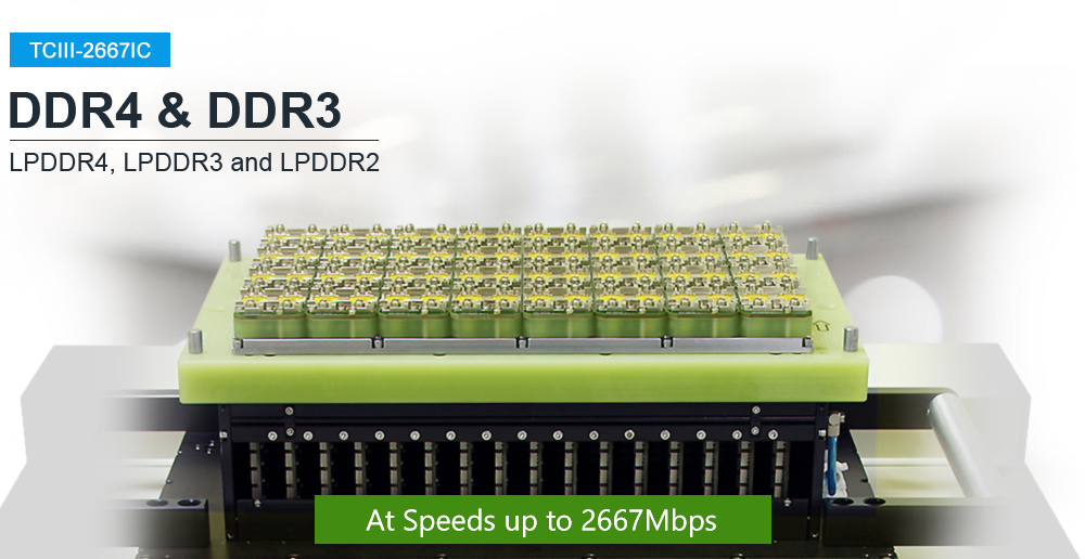

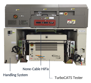
The TCIII-2667IC DDR4 Test System
Supports Data Rates Up To 2667Mbps
DDR4 - supports speeds up to 2667MbpsDDR3 - supports speeds up to 1866MbpsLPDDR4 - supports speeds up to 2667MbpsLPDDR3 - supports speeds up to 1866MbpsLPDDR2 - supports speeds up to 1066Mbps
GUI Failure Analysis
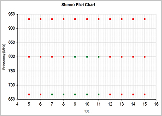
Shmoo Plot
A two-dimensional diagram that shows the status of the DQ bits of Memory ICs varying over a range of the user's selected parameters (timing and input voltage level).
Graphical Identification of Failed DQs' Locations
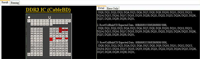
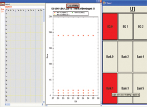
Bit Failure Mapping
A tool that helps the user find the failed DQ bits in the RAM by spotting and displaying the corresponding row and column addresses.
Combination of Failures
- Functional Failure: Cell stuck-at, coupling, neighborhood sensitivity and software error faults
- Parametric Failure: (AC) Speed timing vs. Vdd threshold, (DC) Leakage and Idds
- High Temperature Failure: System in high temperature environment
Script Code Function (optional)
Script Code Debugger
TurboCATS designs a powerful feature called the Script Code in the new DDR3/ DDR4, TCIII-2667IC test system. In the new system, the user can use the script programming language to create a customized test pattern. It can support up to a maximum of 2048 data patterns (optional). Once the pattern is created, the Script Code pattern generator/ compiler is used to compile the code and then generate the new test pattern.
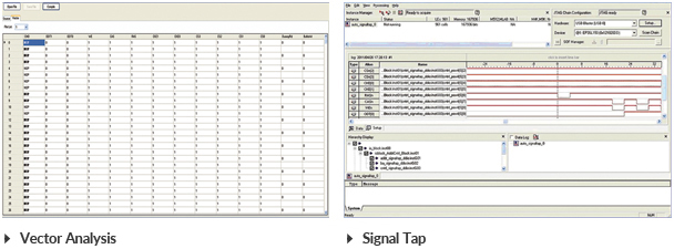
The Script Code function also serves as a powerful compiler/ debug tool. It contains a built-in compiler and debugger for the Script Code programming which allows the customer to monitor the timing waveform of the programming algorithm as well as the timing bus transactions. This is all accomplished with the Signal Tap tool.
The new pattern is then imported into the test list and gives the customer a customized pattern with AC (tSU, tWD, tSAC, tRCD, tCL, tAL, tWR, tRP, tRC, tREF, tRFC, etc.) and DC (Vdd, Vref) parameters for testing their product. In addition to the above, the customer can also create a motherboard test pattern algorithm using the Script Code function.
Multi-Site Networking
Better Technology is Better Business

The TCIII-2667IC multi-site system can be networked so the user can test up to 512 devices using one PC to control the entire operation. This gives the customer greater flexibility in terms of increasing testing capacity on an as-needed basis.
Handler Interface (optional)
Available to be Combined with the TCIII-2667IC Test System
- Supports up to 256 DUTs on DDR3/ DDR4 IC
- Supports up to 128 DUTs on LPDDR IC
- Supports both manual and automated handler testing
M6771AD/ M6741AD Handler
- DDR4/ DDR3/ LPDDR3 up to 64 DUT's or 128 DUT's
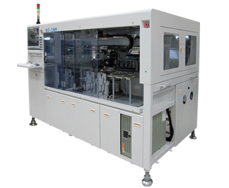
HT-3309 Handler
- LPDDR3 up to 128 DUT's
- DDR3/ DDR4 up to 256 DUT's
Features
Test Capabilities
- DDR4 - 1600Mbps, 1866Mbps, 2133Mbps, 2400Mbps, 2667Mbps
- DDR3 - 1333Mbps, 1600Mbps, 1866Mbps
- LPDDR4 - 1600Mbps, 1866Mbps, 2133Mbps, 2400Mbps, 2667Mbps
- LPDDR3 - 1066Mbps, 1333Mbps, 1600Mbps, 1866Mps
- LPDDR2 - 667Mbps, 800Mbps, 1066Mbps
- Clock frequency from 667MHz to 1066MHz
GUI Failure Analysis Tool
- Graphical Failure display shows Failed bad ICs and DQ pins' location
- Error logging locations of Row/ Column/ Blanks/ Burst/ DQs for analyzing failures
- Address Scramble/ Data Scramble
- Optional tools include Bit Failure Mapping & Schmoo Plot to display the failed Blanks(s)/ DQ bits in the RAM
AC/ DC Parametric & Tests
- Supports ISVM (Contact open pins) and VSIM (Leakage current)
- Supports AC/ DC/ Idds' parametric tests: Continuity, Leakage, Idds' checking
- Over 35 industry standard test patterns and user script pattern programming are available
- Supports SPD programming, Read/ Write test, Write-Protect, etc.
- Auto Timing Calibration calibrates the tester and performs test on different types of ICs
Flexible Configuration
- Configurable from 6-site to 512-site for parallel testing
- Proper chassis design to meet various handlers' requirements
- Supports custom load boards for manual test
- Supports None-Cable HiFix that can be integrated with a selection of handlers' interfaces
- Optional:
- - Environmental tests from low to high temperatures ranging from -30°C to 125°C
- - Heat chamber is available to detect marginal timing and cell storage failures
from
32°C to 85°C
AC Specifications
| Test Frequency | DDR3 DDR4 LPDDR2 LPDDR3 LPDDR4 |
667Mhz to 933Mhz 800Mhz to 1333Mhz 333MHz to 533MHz 533MHz to 933MHz 800MHz to 1333MHz |
|||
| Switching Data Rate | DDR3 DDR4 LPDDR2 LPDDR3 LPDDR4 |
1333Mbps to 1866Mbps 1600Mbps to 2667Mbps 667Mbps to 1066Mbps 1066Mbps to 1866Mbps 1600Mbps to 2667Mbps |
|||
| I/O Interface | DDR3 | SSTL-15, Class I & Class II SSTL-135, Class I & Class II |
|||
| DDR4 | POD-12, 1.2V Pseudo Open Drain I/O | ||||
| LPDDR2 | 1.2V HSTL Class | ||||
| LPDDR3 | 1.2V HSUL | ||||
| Clock Lines | 1 pair per site | ||||
| Address Depth | DDR3 | 16 Rows, 15 Columns, 3 Banks 16X/ 15Y/ 3Z per site |
|||
| DDR4 | 18 Rows, 15 Columns, 4 Banks 18X/ 15Y/ 4Z per site |
||||
| LPDDR2 | 14 Rows, 10 Columns, 3 Banks 14X/ 15Y/ 4Z per site |
||||
| LPDDR3 | 15 Rows, 12 Columns, 3 Banks 15X/ 12Y/ 3Z per site |
||||
| Data Width | 8 I/O; Supports 8/ 16/ 32 bit IC devices | ||||
| DQS's | Differential | ||||
| Control Lines | DDR3, DDR4 |
2 CS's, 2 CLKE, 1 RAS, 1 CAS, 1 WE | |||
| LPDDR2, LPDDR3 |
2 CS's, 2 CLKE, 10 CA pins 2 CS's, 2 CLKE, 10 CA pins, 1 ODT |
||||
| Termination | On-chip, dynamic | ||||
| Variable Timing Edges | tSU/ tHD, tWD, tDQSS, tAC, etc. | ||||
| Programmable Timing | DDR3, DDR4 |
tRCD, tCL, tRL, tWL, tAL, tRP, tRFC, tWR, tCWL, etc. | |||
| LPDDR2, LPDDR3 |
tRCD, tRL, tWL, tAL, tRP, tRFC, tWR etc. | ||||
| SPD Programming | Read, Program, Edit, Test Byte Matching, Serialization, Write-Protect, Slot Test, etc. |
||||
| Control PC Requirements | Windows 7 (64 bit) or better, Networking interface | ||||
| AC Power Source | 110-240VAC, 50/60Hz | ||||
TCIII-2667IC with Heat Chamber (optional)
The heat Chamber creates a high temperature testing environment to simulate the accelerated life testing and analyze the behaviors of the module.
Heat Chamber Specifications
| Power Supply | 220V, 50Hz (90 - 110% of rated voltage) |
| Power Consumption | Power-up: 15A, 220V |
| Normal operation: 10A, 220V | |
| Display Method | Red 7 Segment LED Display |
| Storage Temperature | -20°C - 60°C |
| Ambient Humidity | 35% - 85% RH |
| Temperature Range | 25°C - 85°C |
| Recommended Setting Temperature | 80°C |
| Air Input | Min. 0.5 MPa - Max. 1.0 MPa |
| Min. 75 psi - 145 psi | |
| Diameter of Gas Tube | 6 mm |
Software Screenshots
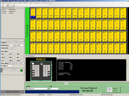
Main Operating Window
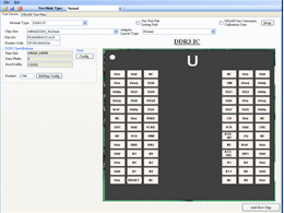
Test Device Configuration
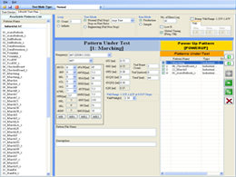
Test Plan
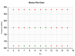
Shmoo Plot Dot
TURBOCATS, LTD. RESERVES THE RIGHT TO CHANGE PRODUCTS, INFORMATION AND SPECIFICATIONS WITHOUT NOTICE. Products and specifications discussed herein are for reference purposes only. All information discussed herein is provided on an "AS IS" basis, without warranties of any kind.