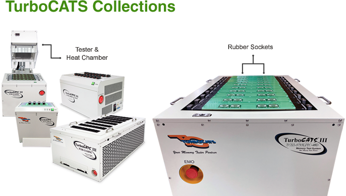
Built To Fit Your Memory Testing Needs
At Speed Test Up to 3733Mbps
To assist manufacturers in their efforts to control costs, TurboCATS proudly introduces the new TCIII-3733LPIC multi-site test system. The TCIII-3733LPIC system comes with two additional new major features: AC switching noise simulation on the LPDDR4/ 4x, and rubber socket option that can lead better test yield while requiring less maintenance. The system can handle up to 128 devices, which offers high-production throughput. We also offer a handler interface option in sorting and binning for the system.
Customizable Features
- LPDDR4 - 1600Mbps, 2133Mbps, 2400Mbps, 2667Mbps, 3200Mbps, 3733Mbps
- LPDDR3 - 1066Mbps, 1333Mbps, 1600Mbps, 1866Mbps, 2133Mbps
- DDR4 - 1600Mbps, 1866Mbps, 2133Mbps, 2400Mpbs, 2667Mbps, 2866Mbps, 2933Mbps, 3200Mbps
- DDR3 - 1066Mbps, 1333Mbps, 1600Mbps, 1866Mbps, 2133Mbps
- Clock frequency from 533MHz to 1866MHz
- Configurable from 4-site to 128-site for parallel testing
- Optional heat chamber and rubber-sockets handler docking
- Proper chassis design to meet various selective handlers requirement
What is Rubber Sockets?
Breakthrough High Speed Testing Technology

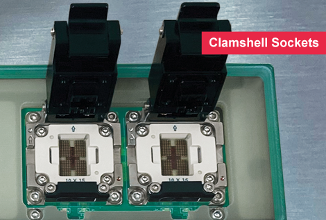
Rubber Sockets support high speeds up to 16GHz - Supports Clamshell Sockets
- Supports a wide-range temperature
- A better yield with non-damaging solder balls on DUTs
- Less maintenance is required
- More flexibility for finer pitch capability
eMCP Function
eMMC + LPDDR4/ LPDDR3
- LPDDR4/ LPDDR3 and eMMC are tested Interactively or individually by different adaptor boards
- Interactive Test by eMCP(LPDDR4/ 4x + eMMC) DUT board
- Individual Test by eMMC DUT board
- Supports eMMC formatting flow for eMMC card settings
- Easy to reconfigure different types of packages and devices
- - DC Patterns test: LPDDR4/ 4x ONLY
- - Device Functional test: LPDDR4/ 4x and eMMC
- - DC Patterns test: eMMC ONLY
- - Device Functional test: eMMC ONLY
Multi-Site Networking
Solutions for your Connected Testing
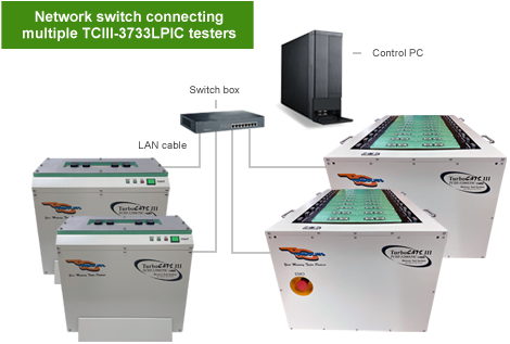
The TCIII-3733LPIC (LPDDR4/ LPDDR3) IC test system can be networked so the user can test up to 128 devices using one PC to control the entire operation. This gives the customer greater flexibility in terms of increasing testing capacity on an as-needed basis.
GCOM-128D IC Handler Interface (optional)
Supports LPDDR4/ LPDDR3
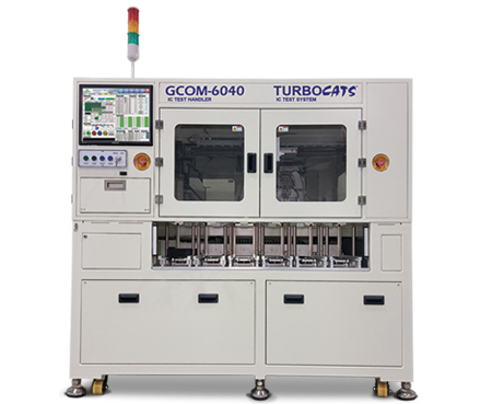
Enchancement Features
- A tray Pick-and-Place type IC handler
- Supports different types of ICs, run in automation test
- Drag and drop operation
- Loading & Unloading robot
- Shuttle buffer
- Tray Stacker
- Extremely intuitive software GUI
- Click here for more information
Features
Testing Capabilities
- LPDDR4 - 1600Mbps, 2133Mbps, 2400Mbps, 2667Mbps, 3200Mbps, 3733Mbps
- LPDDR3 - 1066Mbps, 1333Mbps, 1600Mbps, 1866Mbps, 2133Mbps
- DDR4 - 1600Mbps, 1866Mbps, 2133Mbps, 2400Mpbs, 2667Mbps, 2866Mbps, 2933Mbps, 3200Mbps
- DDR3 - 1066Mbps, 1333Mbps, 1600Mbps, 1866Mbps, 2133Mbps
- Clock frequency from 533MHz to 1866MHz
Flexible Configuration
- Configurable from 4-site to 128-site for parallel testing
- Proper chassis design to meet various selective handlers requirement
- Optional environmental tests high temperatures ranging from 25˚C to 125˚C
- Supports speed tests from 1600Mbps to 3733Mbps for LPDDR4/ 4x
- Optional heat chamber and rubber-socket handler docking
GUI Failure Analysis Tool
- Failed IC's and DQ's
- Error Logging
- Bit Mapping
- Shmoo Plot
- Eye Diagram
DC & AC Parametric Tests
- Supports VSIM
- Continuity, Leakage, Idd's measurement
- Over 35 industry standard test patterns
- User-defined AC patterns programming
- Auto Timing Calibration
- Application Tests
- - Calibration and Self Training
- - AC Switching Noise Simulation
- - Boot Vector (e.g., Boot Vector Patterns)
Boot Vector Patterns
- TurboCATS has developed a new circuit in the TCIII-3733LPIC system to emulate the platforms boot up sequence. This pattern can detect errors from memory devices during boot up sequence.
We have also developed two other application patterns as well in the TCIII-3733LPIC test system that can detect errors from the memory devices:
A) Calibration test: Detects self training problemB) High Noise Simulation: Detects any switching noise problem
Powerful Integration Tool
eMCP Function
- LPDDR4/ 4x, LPDDR3 and eMMC
- LPDDR4: 3733Mbps
- eMMC Application Flow
- LPDDR3: 2133Mbps
GUI Failure Analysis
Graphical Identification of Failed DQs' Locations
Represents the failed DQ pins locations, graphically. The software uses a graphical picture to show the test failures at the hardware level: If the IC fails during the test, there would be indications (displayed in RED) marking the failed pin(s) and signal(s).
Address/ Data Logging
Error logging can analyze failures by using address and data information.

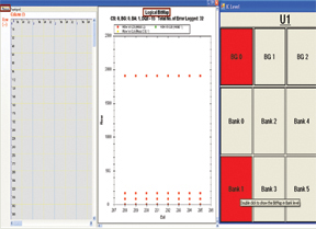
Bit Failure Mapping
A tool that helps the user to find and display the failed DQ bits in the RAM. The corresponding row and column addresses the failed DQ bits, which will be spotted and displayed for the user.
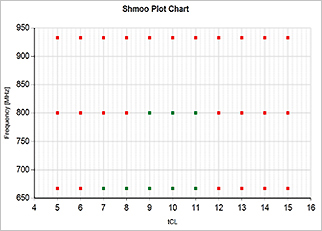
Shmoo Plot
A two-dimensional diagram that shows the status of the DQ bits of Memory ICs varying over a range of the user's selected parameters (timing and input voltage level).
Pattern Programming Function (optional)
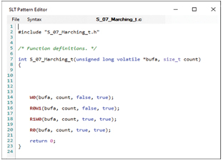
The customer can use a C++ programming language to create a customized AC Command pattern. The programming function also serves as a powerful compiler/debug tool for Pattern programming and allows the user to monitor the timing waveform of the algorithm along with the timing bus transactions. This is all accomplished under the Software.
Specifications: LPDDR4 & LPDDR4x
| Test Frequency | LPDDR4, 800Mhz to 1600/ 1866 MHz | |||
| Switching Data Rate | LPDDR4, 1600Mbps to 3200/ 3733 Mbps | |||
| I/O Interface | LPDDR4, Supports LVSTL | |||
| Clock Lines | 1 pair per site | |||
| Address Depth | LPDDR4/ 4x: | 17 Rows, 10 Columns, 3 BAs (17X/ 10Y/ 3Z) per site | ||
| Data Width | 16 DQs/ 32 DQs | |||
| Termination | On-chip, dynamic | |||
| Variable Timing Edges | tRCD, tCL, tRL, tWL, tAL, tRP, tRFC, tWR, tCWL, etc | |||
| Programmable Timing | tRCD, tRP, tCCD, tRL, tFAW, tWTR, tRAS, tRTP, tRFC, etc | |||
Specifications: LPDDR3
| Test Frequency | LPDDR3, 667Mhz to 1066Mhz | |||
| Switching Data Rate | LPDDR3, 1333Mbps to 2133Mbps | |||
| I/O Interface | LPDDR3, 1.2V HSUL | |||
| Clock Lines | 1 pair per site | |||
| Address Depth | LPDDR3: | 15 Rows, 12 Columns, 3 BAs (15X/ 12Y/ 3Z) per site | ||
| Data Width | 16 DQs/ 32 DQs | |||
| Termination | On-chip, dynamic | |||
| Variable Timing Edges | tRCD, tCL, tRL, tWL, tAL, tRP, tRFC, tWR, tCWL, etc | |||
| Programmable Timing | tRCD, tRP, tCCD, tRL, tFAW, tWTR, tRAS, tRTP, tRFC, etc | |||
Specifications: eMMC
| Speed Mode | Supports High Speed, HS200 and HS400 |
| Operating Voltage | Vcc Range: 2.35V to 3.3V |
| VccQ Range: 1.6V to 1.95V | |
| Test Function | Interactive Test by eMCP (LPDDR4/4x + eMMC) DUT Board - DC Patterns Test: LPDDR4/4x only - Device Functional Test: LPDDR4/4x and eMMC |
| Individual Test by eMMC DUT Board - DC Patterns Test: eMMC only - Device Function Test: eMMC only |
|
| Read ID Function | CID (Device Identification Register) Read |
| CSD (Device Specific Data) Read | |
| Extended CSD Register Read | |
| User Function | Device Erase, Write and Read function: - User can define the percentage of Erase/ Write/ Read area in User Test-Pattern programming. |
Specifications: DDR3 & DDR4
| Test Frequency | DDR3 - 667Mhz to 933Mhz |
| DDR4 - 800Mhz to 1333/ 1600Mhz | |
| Switching Data Rate | DDR3 - 1333Mbps to 1866Mbps |
| DDR4 - 1600Mbps to 2667/ 3200Mbps | |
| I/O Interface | DDR3 - SSTL-15, Class I & Class II |
| DDR3 - SSTL-135, Class I & Class II | |
| DDR4 - POD12-1.2V Pseudo Open Drain I/O | |
| Clock Lines | 1 pair per site |
| Address Depth | DDR3 - 16 Rows, 15 Columns, 3 BAs (16X/15Y/3Z) per site |
| DDR4 - 18 Rows, 15 Columns, 4 BAs (18X/15Y/4Z) per site | |
| Data Width | 4 DQs / 8 DQs / 16 DQs / 32 DQs |
| Termination | On-chip, dynamic |
| Variable Timing Edges | tSU/tHD, tAC (tDS/DH), tDQSS, tWD, etc |
| Programmable Timing | tSU/tHD, tWD, tDQSS, tAC, tSREF, tREF, etc |
Minimum Hardware Requirements
| External PC requirements | Execute TCIII-3733LPIC software to control station operation Windows 10, 64-bit, build ver. 2004 operating system or above. | |||
| PC Minimum Requirements: - CPU: Quad-core Intel/ AMD CPU with clock freq. at least 3.60 GHz (Intel Core i5-6500 or AMD equivalent) - RAM: 8 GB, HDD Space: 60GB - 1920 x 1080 Resolution capable display |
||||
| Recommended Requirements - CPU: Hexa-core Intel/ AMD CPU with clock freq. at least 4.00 GHz (Intel Core i5-8400 or AMD equivalent) - RAM: 16GB, HDD Space:100GB - 1920 x 1080 Resolution capable display or above |
||||
| Remark: The configuration of PC will affect the testing efficient. | ||||
| AC Power Source | 110-240V (AC), 50/60Hz | |||
| Recommended Temperature | 16°C to 32°C (60.8°F to 89.6°F) | |||
| Humidity Limitation | 20% to 80% | |||
TCIII-3733LPIC & Heat Chamber (optional)
The heat chamber creates a high temperature testing environment to simulate the accelerated life testing and analyze the behaviors of the module.
Heat Chamber Specifications
| Power Supply | 220V, 50Hz (90 - 110% of rated voltage) |
| Power Consumption | Power-up: 15A, 220V |
| Normal operation: 10A, 220V | |
| Display Method | Red 7 Segment LED Display |
| Storage Temperature | -20°C - 60°C |
| Ambient Humidity | 35% - 85% RH |
| Temperature Range | 25°C - 85°C |
| Recommended Setting Temperature | 80°C |
| Air Input | Min. 0.5 MPa - Max. 1.0 MPa |
| Min. 75 psi - 145 psi | |
| Diameter of Gas Tube | 6 mm |
Software Screenshots
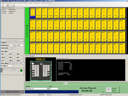
Main Operating Window
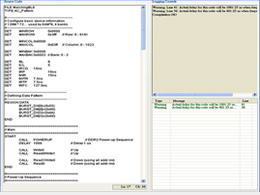
Scrip Code Program
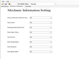
Mechanic Information Setting
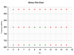
Shmoo Plot
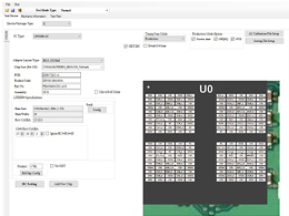
Test Device
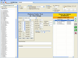
Test Plan
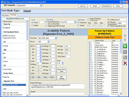
Test List
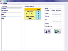
Security Privilege
TURBOCATS, LTD. RESERVES THE RIGHT TO CHANGE PRODUCTS, INFORMATION AND SPECIFICATIONS WITHOUT NOTICE. Products and specifications discussed herein are for reference purposes only. All information discussed herein is provided on an "AS IS" basis, without warranties of any kind.

